This note mainly covers mathematical concepts that may appear in rendering, CG, and Shader. It does not cover various basic mathematical concepts in full, and there are almost no formulas—it focuses more on conceptual understanding and possible applications in rendering.
Linear Algebra
Vectors
The basic concept of vectors will not be elaborated here. The following concepts are commonly used:
- Dot product: Because the dot product is computed as the product of the magnitudes multiplied by the cosine of the angle between them, if both vectors are unit vectors, the dot product result equals cosθ. Therefore, when discussing unit vectors, we can treat the dot product as a proxy for the angle.
- Cross product: An important property of the cross product is that the result is perpendicular to both operands. In a right-handed coordinate system, curl your fingers from vector a to vector b, and your thumb points in the direction of a × b. The cross product can be used to find normals and to determine triangle face orientation.
Vectors and points are both expressed as ordered pairs of numbers. In the case of 3D vectors/points, using pure mathematical notation alone, we cannot tell whether (1,2,3) refers to a point or a vector. We will later use homogeneous coordinates to resolve this.
Matrices
Again, conceptual details are omitted. The computation of matrix multiplication is also omitted. The following concepts are commonly used:
- Inverse matrix: Whether a matrix is invertible is determined by its determinant. If detM ≠ 0, then matrix M is invertible. In Shader we have ample third-party libraries to compute the determinant, so the calculation is not detailed here. The inverse matrix is used to apply the reverse of a transformation.
- Order of computation: For a transformation CBAv, we first apply A to vector v, then B, then C. Here, v must be a column vector. Note that in most cases composite transformations do not commute, so the order above cannot be rearranged.
- In the vast majority of cases, we scale first, then rotate, then translate.
Homogeneous Coordinates
Homogeneous coordinates add a fourth value w after the three spatial coordinates to enable computation, turning affine transformations into linear transformations. Homogeneous coordinates were introduced to handle non-linear transformations such as translation.
- Linear transformation: A transformation f satisfying both of these conditions is called linear: f(x) + f(y) = f(x+y) and kf(x) = f(kx)
- Affine transformation: Any transformation of the form f(x) = Ax + b is called an affine transformation.
Note: For points, the extra component w = 1; for vectors, w = 0. Thus, translating a point yields a point; translating a vector still yields a vector, and in practice has no effect. So points and vectors are formally distinct in homogeneous coordinate space.
Coordinate Space Transformations
In Shader, coordinate space transformations are perhaps the most important. Suppose we want to convert between coordinate spaces A and B.
To transform point x_A from coordinate system A to B, we use the transformation matrix MATRIX_A2B:
x_B = MATRIX_A2B * x_A
To transform point y_B from coordinate system B to A, we use the transformation matrix MATRIX_B2A:
y_A = MATRIX_B2A * y_B
This must be understood clearly. The transformation matrix is a transformation and must be placed on the left of the vector for left multiplication. The transformation matrix goes from the source coordinate system to the target coordinate system. Hence the results above.
In general, the transformation matrices for various coordinate systems we encounter in Shader are already built-in. We mainly need to know how many different coordinate systems we may encounter when writing Shaders.
Vertex Transformation Pipeline
In Unity and other computer graphics rendering systems, a vertex on a model must go through multiple transformations before it appears on screen and is rendered in a pixel.
In this process, it starts in model space, is then transformed to world space, then to view space, then to clip space, and finally to screen space.
Model Space
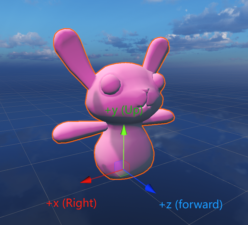
Model Space (also called Local Space) is the space in which the artist models. A certain point is chosen as the origin, and the positive directions of the x, y, z axes are defined. In Unity, when you select an object, the three axes and pivot that appear represent the model space axes and origin. Every point on the object has its own coordinates relative to this origin and these axes.
World Space and Model-to-World Transform
In general, world space is the "outermost" space in Unity. If a GameObject has no parent, its Transform Position is its world space coordinate.
Model-to-World Transform / Model Transform
The Model Transform (M) converts vertices from model space to world space. In Unity, the predefined variable _Object2World in UnityShaderVariables.cginc, when left-multiplied with model space coordinates, converts them to world space. We can abbreviate this matrix as the M matrix.
View Space and World-to-View Transform
View Space (also called Camera Space) uses the camera as the origin, with +x to the camera's right, +y upward, and +z pointing behind the camera. In other words, the camera's forward direction is the -z direction in view space, which means view space uses a different handedness than the previous two spaces. The first two are left-handed, while view space is right-handed.
World-to-View Transform / View Transform
The View Transform (V) converts vertices from world space to view space. In Unity, the predefined variable UNITY_MATRIX_V in UnityShaderVariables.cginc, when left-multiplied with world space coordinates, converts them to view space. We can abbreviate this matrix as the V matrix.
Clip Space and Projection Transform
Clip Space (P), also called homogeneous clip space, is used to cull primitives outside the view frustum and to clip primitives that intersect the frustum boundaries.
The View Frustum is the camera's visible range in Unity, bounded by 6 planes. The plane closest to the camera is the Near Clip plane, and the farthest is the Far Clip plane.
Unity has two rendering modes: in Orthographic mode, the near and far planes have the same size; in Perspective mode, the far plane is larger than the near plane.
As mentioned earlier, for a vertex, the homogeneous w component is 1. In Unity, you can left-multiply view space coordinates by UNITY_MATRIX_P to transform them from view space to clip space. Orthographic and perspective projection use different projection matrices. The key differences are:
- In orthographic projection, the w component is transformed by the projection matrix to -z, with different scaling applied to xyz.
- In perspective projection, the w component remains 1.
The perspective matrix changes the handedness of space from right-handed to left-handed, so the farther from the camera, the larger z becomes.
The perspective matrix depends on the camera's near and far plane positions, aspect ratio, and field of view.
Clip Space to Screen Space
The final step is to transform vertices to 2D screen space. This is done in two steps:
Step 1: Homogeneous Division
Transform x, y, z to x/w, y/w, z/w. The resulting coordinates are called Normalized Device Coordinates (NDC). The view frustum becomes a cube after this transformation.
Step 2: Screen Mapping
In Unity, after the first step, the x and y coordinates fall within [-1, 1]. We only need to map (x, y) to screen space where x ∈ [0, width] and y ∈ [0, height].
At this stage, the z component may be used for the depth buffer.